Discontinued On Mar. 2015
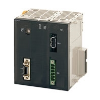
CJ1W-MCH71
CJ-series Motion Control Unit with MECHATROLINK-II interface
Improve Equipment Design Efficiency and Shorten Tact Time
* Information in this page is a reference that you created on the basis of information in the product catalog before the end of production, may be different from the current situation, such as goods for / supported standards options / price / features of the product. Before using, please check the compatibility and safety system.
Related Contents
- Features
- Lineup
- Specifications
- Dimensions
- Catalog / Manual / CAD / Software
last update: November 1, 2012
General Specifications
| Item | Specifications |
|---|---|
| Model | CJ1W-MCH71 |
| Power supply voltage | 5 VDC (from Backplane) |
| 24 VDC (from external power supply) | |
| Voltage fluctuation tolerance | 4.5 to 5.5 VDC (from Backplane) |
| 21.6 to 26.4 VDC (from external power supply) | |
| Internal current consumption | 5 VDC 0.6 A max. |
| Weight (Connectors excluded) | 210 g max. |
| Safety standards | UL, CSA, C-TICK, and EC Directives. |
| Dimensions (mm) | 90 (H) × 79.8 (W) × 65 (D) (single) |
| Altitude | At 2,000 m elevation or lower. |
Specifications other than those shown above conform to the general specifications for the CJ series.
Functions and Performance Specifications
| Item | Specifications | |
|---|---|---|
| Applicable PLC | CJ-series PLCs with CPU Units with unit version 2.0 or later | |
| Type of Unit | CPU Bus Unit | |
| Mounting | CPU unit or expansion rack | |
| Number of Units | One CJ1W-MCH71 Motion Control Unit requires the space of three standard Unit. | |
|
Method for data transfer with CPU Unit |
CIO Area for CPU Bus Unit |
Occupies the area for 1 unit (25 words) |
| For units and tasks: 11 to 25 words (Depending on the number of motion tasks) | ||
|
DM Area for CPU Bus Unit |
Occupies the area for 1 unit (100 words) | |
| For units and tasks: 32 to 74 words (Depending on the number of motion tasks) | ||
| Custom Bit Area | For axes: 0-64 words (Depending on the greatest number of the axis used) | |
| Custom Data Area | For axes: 0-128 words (Depending on the greatest number of the axis used) | |
| Custom Data Area | For General I/O: 0-1280 words (Depending on setting) | |
| Controlled Devices | MECHATROLINK-II below supported W-series Servo Driver with built-in communications functions W-series Servo Driver (OMRON) + Communications I/F Unit (YASKAWA) Various I/O units (YASKAWA) SMARTSTEP Junior Servo Drive Up to 30 nodes * When MECHATROLINK-II devices are connected up to 16 nodes (within 30 m) or 15 nodes (within 50m), a repeater unit is not required. A repeater unit is required to connect MECHATROLINK-II devices more than the cases described above. |
|
| Built-in program language | Dedicated motion control language | |
| Control | Control method | MECHATROLINK-II Position commands, Speed commands, Torque commands |
|
Number of controlled axes |
32 axes max. Physical axes/Virtual axes: 30 axes max. (Either can be selected for each axis) Dedicated for virtual axes: 2 axes |
|
| Operating modes | RUN mode, CPU mode, Tool mode/System (Depending on the tool) | |
| Automatic/Manual Mode | Automatic mode: Executing built-in programs of MC Unit controls motion. Manual mode: Executing commands from CPU Unit (PC interface area) controls motion. Note: The Automatic or Manual Mode is set according to the PC Interface area of the CPU Unit. |
|
| Control unit | Minimum setting unit | 1, 0.1, 0.01, 0.001, 0.0001 |
| Units | mm, inch, deg, pulse | |
| Maximum position command value | -2147483647 to 2147483647 pulses (signed 32-bit) Mode for unlimited axes feeding is possible. Example: With 16-bit encoder (65536 pulse/rev), Minimum setting unit: 0.001 mm, 10 mm/rev, the position command value range will be from -327679999 to 327679999 command units. |
|
|
Control operations based on commands from the CPU Unit |
Servo lock/unlock | Executes Servo driver lock or unlock |
| Jogging | Executes continuous feeding independently for each axis, by means of speed set in system parameter x override. |
|
| STEP operation | Feeds a specified distance for a specified axis. | |
| Origin search | Defines the machines origin according to the search method set in the system parameters. | |
| Forced origin | Forcibly sets the present position to 0 to establish it as the origin. | |
| Absolute origin setting | Sets the origin when an absolute encoder is used. Offset value: Signed 32-bit (pulses) |
|
| Error counter reset | Forcibly resets the error counter to 0. | |
| Present position preset | Sets the present position to a user-specified value. | |
| Machine lock | Prohibits the output of motion commands to the axes. | |
| Single block | Executes the motion program one block at a time. | |
| Auto/manual change | Switches between auto mode and manual mode. | |
|
Control Operations according to motion program |
Positioning (PTP) | Executes positioning independently for each axis at the speed set in the system parameters. Simultaneous specification: 8 axes max. /block Simultaneous execution: 32 blocks max. /unit |
| Linear interpolation | Executes linear interpolation for up to 8 axes simultaneously at the specified interpolation speed. Simultaneous specification: 8 axes max. /block Simultaneous execution: 32 blocks max. /system |
|
| Circular interpolation | Executes clockwise or counterclockwise circular interpolation for two axes at their specified interpolation speed. Simultaneous specification: 2 or 3 axes/block Simultaneous execution: 16 blocks max. /system |
|
| Origin search | Defines the machine origin according to the search method set in the system parameters. An offset can be specified for the position after the origin search. The absolute encoder can also execute origin search. |
|
| Interrupt feeding | By means of inputs to the servo driver, moves a specified axis for a specified travel distance to perform positioning. |
|
| Time-specified Positioning | Executes positioning with time specified. | |
| Traverse function | Performs winding operation (traverse control) with two specified axes. | |
|
Electronic Cam, Single Axis |
Execute cam operation according to the specified cam table data with reference to elapse of time. |
|
|
Synchronous Electronic cam |
Executes cam operation according to the specified cam table data with reference to the position of the specified axis. |
|
| Link operation | Executes link operation according to set conditions with reference to the position of the specified axis. |
|
| Electronic Shaft | Executes synchronous operation at a speed calculated with the speed of the specified axis and gear ratio. |
|
|
Trailing synchronous operation |
Executes trailing + synchronous operations with reference to the position of the specified axis. | |
| Speed command | Outputs speed commands to the specified axis. | |
| Torque command | Outputs torque commands to the specified axis. | |
| Acceleration/deceleration curve | Trapezoidal or S-shape | |
|
Acceleration/ deceleration time |
Acceleration/ deceleration time |
60000 ms max. |
| S-shape time constant | 30000 ms max. | |
| External I/O |
For high-speed servo communication bus |
One port for MECHATROLINK-II |
| Servo encoder | Incremental rotary encoder Absolute rotary encoder (Unlimited length ABS supported with some conditions) |
|
| I/O | Deceleration stop input (or servo-OFF stop): 1 pt General input: 2 pts General output: 2 pts |
|
|
External power supply for I/O |
24 V | |
| Feed rate | Rapid feed rate | 1 to 2147483647 [Command unit/min] |
| Interpolation feed rate | 1 to 2147483647 [Command unit/min] | |
| Override | Changes the operation speed by applying a given factor to the speed specified by the system parameters or the motion program. 0.00 to 327.67% (Setting unit: 0.01%, can be specified for each axis or task) |
|
|
Internal override (supported for unit version 3.1 and later) |
The feed rate of the following commands can be set by the motion program. Command: Rate to which override is applied MOVE: Rapid feed rate DATUM: Origin return feed rate MOVEI: Rapid feed rate, external positioning rate MOVET: Rapid feed rate The actual feed rate is calculated using the following formula. Actual feed rate = Axis feed rate × (Axis override + Internal override) |
|
| Axis control | Backlash compensation | Compensates mechanical backlash (the mechanical play between driving and driven axes) with a value registered in advance. This function uses a parameter in the servo driver. |
| In-position | This function is used whether a positioning is completed or not. This function uses a parameter in the servo driver. |
|
| Position loop gain | This is the position loop gain of the servo driver. This function uses a parameter in the servo driver. |
|
| Feed forward gain | The command values created in the MC Unit are multiplied by this feed forward gain. This function uses a parameter in the Servo Driver. |
|
| Program | Number of tasks | Motion task: 8 tasks max. |
|
Parallel branching in task |
Motion task: 8 branches max. | |
| Number of programs | 256 programs max. /unit The program Nos. used for programs are from 0000 to 0999. |
|
| Program numbers | 0000 to 0499: Main programs for motion tasks 0500 to 0999: Sub-programs for motion tasks |
|
| Program capacity | 2 Mbytes 8000 blocks max. /unit by motion program conversion. |
|
| Number of blocks | 800 blocks/program | |
| Position data capacity | 10240 points/unit | |
| Sub-program nesting | 5 levels max. | |
| Start | Starts program operation from program (of another task) | |
| Start mode | Motion task: Initial, continue, next | |
| Deceleration stop | Motion task: Executes deceleration stop regardless of block | |
| Block stop | Motion task: Executes deceleration stop at the end of the block currently being executed. | |
| Single-block mode | Motion task: the program is executed one block at a time. | |
|
Breakpoints (supported for unit version 3.0 and later.) |
Breakpoints can be set for any block using the Support Tool. When a breakpoint is set for a block, program execution will stop after that block has been executed. |
|
|
Saving program data |
MC Unit | Flash memory backup |
|
Zones (supported for unit version 3.0 and later.) |
The zone bit turns ON when any variable (including feedback present position, feedback speed, etc.) is within the set range, and OFF when outside of the set range. A maximum of 32 zones can be set. |
|
|
Data tracing (supported for unit version 3.0 and later.) |
A maximum of two groups can be simultaneously traced, with 1 to 16 data items in each group. Note: The items that can be traced are bits and data. These are each handled as a single item. The number of data samples that can be collected is 2,048 samples when 16 items are set for tracing to 32,768 when only 1 item is set for tracing. |
|
| Self-diagnostic function | Watchdog, FLASH-ROM check, RAM check, etc. | |
| Error detection function | Deceleration stop input, unit number error, CPU Unit error, software limit over errors, etc. | |
| Error log function | The error log is to be read from the CPU Unit by means of the IORD instructions as needed. | |
| Alarm reset | Alarm reset | |
|
Program and CAM data read protection (supported for unit version 3.1 and later) |
Third party access to program and CAM data can be restricted using the CX-Motion-MCH version 2.1 read protection function (password setting). |
|
last update: November 1, 2012
 Product Category
- Automation Systems
-
Programmable Controllers
-
Discontinued
- CJ1W-MCH71
-
Discontinued
-