G9SX-GS
Safety Guard Switching Unit
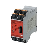
A Safety Measure for Hazardous Operations That Does Not Lower Productivity
Related Contents
- Features
- Lineup
- Specifications
- Dimensions
- Catalog / Manual / CAD / Software
last update: December 23, 2024
Ratings
Power Input
| Model | G9SX-GS226-T15-[] | G9SX-EX-[] |
|---|---|---|
| Rated supply voltage | 24 VDC | |
| Operating voltage range | -15% to 10% of rated supply voltage | |
| Rated power consumption *1 | 5 W max. | 2 W max. |
*1. Power consumption of loads not included.
Inputs
| Model | G9SX-GS226-T15-[] |
|---|---|
| Safety inputs | Operating voltage: 20.4 VDC to 26.4 VDC, Internal impedance: Approx. 2.8 kΩ *2 |
| Mode selector input | |
| Feedback/reset input |
*2. Provide a current equal to or higher than that of the minimum applicable load of the connected input control device.
Outputs
| Model | G9SX-GS226-T15-[] |
|---|---|
| Instantaneous safety outputs *3
OFF-delayed safety outputs *4 |
P channel MOS-FET outputs
Load current: 0.8 A DC max./output *5, 6 |
| Auxiliary outputs
(for input, output, and error monitoring) |
PNP transistor output
Load current: 100 mA DC max. |
| External indicator outputs | P channel MOS-FET outputs
Connectable indicators • Incandescent lamp: 24 VDC, 3 to 7 W • LED lamp: 10 to 300 mA DC/output |
*3. While safety outputs are in the ON state, the following signal sequence is output continuously for diagnosis.
When using the safety outputs as input signals to control devices (i.e. Programmable Controllers), consider the OFF pulse shown below.
*4. When the safety inputs of G9SX are restored during off-delay time, G9SX will operate as below depending on the reset mode.
- Auto reset mode: Outputs turn off after off-delay time, then immediately turns on.
- Manual reset mode: Outputs turn off after off-delay time, then turn on when reset input is given.
*5. The following derating is required when Units are mounted side-by-side.
G9SX-GS226-T15-[]: 0.4 A max. load current/output
*6. The following derating is required when inductive load is connected to safety outputs.
- IEC/EN60947-5-1 DC-13: 0.8 A
- UL508 Pilot Duty: 0.5 A
Expansion Unit
| Model | G9SX-EX-[] |
|---|---|
| Rated load | 250 VAC, 3 A/30 VDC, 3 A (resistive load) |
| Rated carry current | 3 A |
| Maximum switching voltage | 250 VAC, 125 VDC |
Characteristics
| Model | G9SX-GS226-T15-[] | G9SX-EX-[] | |
|---|---|---|---|
| Overvoltage category
(IEC/EN 60664-1) |
II | II (Safety relay outputs 13 to 43 and
14 to 44: III) |
|
| Operating time
(OFF to ON state) *1 |
50 ms max. (Safety input: ON) *2
100 ms max. (Logical AND connection input: ON) *3 |
30 ms max. *4 | |
| Response time
(ON to OFF state) *1 |
15 ms max. | 10 ms max. *4 | |
| Allowable switching time for mode
selector input *5 *7 |
450 ms max. | --- | |
| Response time for switching
operating modes *6 *7 |
50 ms max. | --- | |
| ON-state residual voltage | 3.0 V max. for safety outputs, auxiliary outputs, and external indicator outputs | ||
| OFF-state leakage current | 0.1 mA max. for safety outputs and auxiliary outputs, 1 mA max. for external
indicator outputs |
||
| Maximum wiring length of safety
input and logical AND input |
100 m max.
(External connection impedance: 100 Ω max. and 10 nF max.) |
||
| Reset input time
(Reset button pressing time) |
100 ms min. | ||
| Accuracy of OFF-delay time *8 | Within ± 5% of the set value | ||
| Insulation
resistance |
Between logical AND
connection terminals, and power supply input terminals and other input and output terminals connected together |
20 MΩ min. (at 100 VDC) | --- |
| Between all terminals
connected together and DIN track |
100 MΩ min. (at 500 VDC) | ||
| Dielectric
strength |
Between logical AND
connection terminals, and power supply input terminals and other input and output terminals connected together |
500 VAC for 1 min | --- |
| Between all terminals
connected together and DIN track |
1,200 VAC for 1 min | ||
| Between different
poles of outputs |
--- | ||
| Between safety relay
outputs connected together and other terminals connected together |
2,200 VAC for 1 min | ||
| Vibration resistance | Frequency: 10 to 55 to 10 Hz, 0.375-mm single amplitude (0.75-mm double
amplitude) |
||
| Shock
resistance |
Destruction | 300 m/s2 | |
| Malfunction | 100 m/s2 | ||
| Durability | Electrical | --- | 100,000 cycles min.
(rated load, switching frequency: 1,800 cycles/hour) |
| Mechanical | --- | 5,000,000 cycles min.
(switching frequency: 7,200 cycles/ hour) |
|
| Ambient operating temperature | - 10 to 55 °C (with no icing or condensation) | ||
| Ambient operating humidity | 25% to 85% | ||
| Terminal tightening torque *9 | 0.5 Nm | ||
| Weight | Approx. 240 g | Approx. 165 g | |
*1. When two or more Units are connected by logical AND, the operating time and response time are the sum total of the
operating times and response times, respectively, of all the Units connected by logical AND.
*2. Represents the operating time when the safety input turns ON with all other conditions set.
*3. Represents the operating time when the logical AND input turns ON with all other conditions set.
*4. This does not include the operating time or response time of Safety Guard Switching Units that are connected.
*5. This is the allowable switching time for the operating mode selector. If switching takes more than 450 ms, the G9SX-
GS[] will detect an error.
*6. This is the time required for the safety input to actually switch to an activated condition after the mode selector input is
switched.
*7. Only when the G9SX-GS[] is used with manual switching.
*8. This does not include the operating time or response time of internal relays in the G9SX-EX-[].
*9. For the G9SX-[]-RT (with screw terminals) only.
Logical AND Connection
Note: Please see “Ordering Information” below for the actual models that can be ordered.
| Model | G9SX-GS226-T15-[] | G9SX-EX-[] |
|---|---|---|
| Number of Units connected per logical AND output | 4 Units max. | --- |
| Total number of Units connected by logical AND *1 | 20 Units max. | --- |
| Number of Units connected in series by logical AND | 5 Units max. | --- |
| Max. number of Expansion Units connected *2 | --- | 5 Units max. |
| Maximum cable length for logical AND input | 100 m max. | --- |
*1. The number of G9SX-EX401-[] Expansion Units or G9SX-EX041-T-[] Expansion Units (OFF-delayed Model) not
included.
*2. G9SX-EX401-[] Expansion Units and G9SX-EX041-T-[] Expansion Units (OFF-delayed Model) can be mixed.
last update: December 23, 2024