A165S / W
Knob-type Selector Switch (Detachable) (Cylindrical 16-dia.)
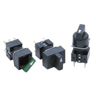
Separate Construction with Cylindrical 16-dia. Body
Related Contents
last update: November 10, 2025
(Unit: mm)
• The Dimension shows 2-switch outputs.
• The lamp terminal is not provided with non-lighted models.
Rectangular A165[]-J
Solder terminals/tab terminals (#110 t=0.5)
Note: See below for panel cutouts.
Square A165[]-A
Solder terminals/tab terminals (#110 t=0.5)
Note: See below for panel cutouts.
Round A165[]-T
Solder terminals/tab terminals (#110 t=0.5)
Note: See below for panel cutouts.
Rectangular A165[]-J
PCB terminals
The lamp terminal is not also provided with nonlighted models.
Note: See below for panel cutouts.
Rectangular A165W[]-T
Reduced-voltage lighting solder terminals/tab terminals (#110 t=0.5)
Rectangular A165[]-2S
Screw-Less Clamp
The lamp terminal is also provided with nonlighted models.
Panel Cutouts
Models with Solder Terminals and Models with Screw-less Clamp Connectors
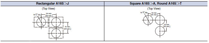
Note: 1. Make sure the thickness of the mounting panel is 0.5 to 3.2 mm.
2. If the panel is to be finished with coating, etc., make sure that the panel meets the specified dimensions after
coating.
3. Figures in parentheses are for screw-less clamp connectors.
2. If the panel is to be finished with coating, etc., make sure that the panel meets the specified dimensions after
coating.
3. Figures in parentheses are for screw-less clamp connectors.
Models with PCB Terminals
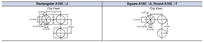
Note: 1. Ensure that the variation in the distance between the centers of neighboring mounting holes is less than ±0.1
mm.
2. Make sure the thickness of the mounting panel is 0.5 to 3.2 mm. If, however, a Switch Guard or Dust Cover is
used, the thickness of the mounting panel must be 0.5 to 2 mm.
3. If the panel is to be finished with coating, etc., make sure that the panel meets the specified dimensions after
coating.
last update: November 10, 2025