EJ1
Modular Temperature Controller
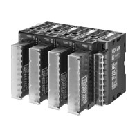
Implement a Multi-Point Control System Easily with Space Saving and Wire Saving by Connecting Modules
Related Contents
- Features
- Lineup
- Specifications
- Dimensions
- Catalog / Manual / CAD / Software
last update: June 24, 2024
Basic Unit/EJ1N-TC
Ratings
| Type | EJ1N-TC4 | EJ1N-TC2 | |
|---|---|---|---|
| Power supply voltage | 24 VDC | ||
| Operating voltage range | 85% to 110% of rated voltage | ||
| Power consumption | 3 W max. (at maximum load) | 2.5 W max. (at maximum load) | |
| Input * | Thermocouple: K, J, T, E, L, U, N, R, S, B, C/W, PLII
ES1B Infrared Thermosensor: 10 to 70°C, 60 to 120°C, 115 to 165°C, 140 to 260°C Analog input: 4 to 20 mA, 0 to 20 mA, 1 to 5 V, 0 to 5 V, 0 to 10 V Platinum resistance thermometer: Pt100, JPt100 |
||
| Input impedance | Current input: 150 Ω max., voltage input: 1 MΩ min. | ||
| Control
outputs |
Voltage output | Output voltage: 12 VDC ±15%, max. load current: 21 mA (PNP models with short-circuit protection circuit) | |
| Transistor output | --- | Max. operating voltage: 30 VDC,
max. load current: 100 mA |
|
| Current output | --- | Current output range: 4 to 20 mA or 0 to 20 mA DC
Load: 500 Ω max. (including transfer output) (Resolution: Approx. 10,000) |
|
| Event
inputs |
Input points | --- | 2 |
| Contact input | --- | ON: 1 kΩ max., OFF: 100 kΩ min. | |
| Non-contact input | --- | ON: Residual voltage: 1.5 V max.,
OFF: Leakage current: 0.1 mA max. |
|
| --- | Outflow current: Approx. 4 mA per point | ||
| Number of input and control
points |
Input points: 4, Control points: 4 | Input points: 2, Control points: 2 | |
| Setting method | Via communications | ||
| Control method | ON/OFF control or 2-PID (with autotuning, self-tuning) | ||
| Other functions | Two-point input shift, digital input filter, remote SP, SP ramp, manual manipulated
variable, manipulated variable limiter, interference overshoot adjustment, loop burnout alarm, RUN/STOP, banks, I/O allocations, etc. |
||
| Ambient temperature range | Operating: -10°C to 55°C, Storage: -25°C to 65°C (with no icing or condensation) | ||
| Ambient humidity range | Operating: 25% to 85% (with no condensation) | ||
* Inputs are fully universal. Therefore, platinum resistance thermometer, thermocouple, infrared thermosensor, and analog
input can be selected.
input can be selected.
Characteristics
| Indication accuracy | Thermocouple input: (±0.3% of indication value or ±1°C, whichever is greater)
±1 digit max. *1 Platinum resistance thermometer input: (±0.2% of indication value or ±0.8°C, whichever is greater) ±1 digit max. Analog input: ±0.2% FS ±1 digit max. CT input: ±5% FS ±1 digit max. |
|
|---|---|---|
| Hysteresis | 0.1 to 999.9 EU (in units of 0.1 EU) *2 | |
| Proportional band (P) | 0.1 to 999.9 EU (in units of 0.1 EU) *2 | |
| Integral time (I) | 0 to 3,999 s (in units of 1 s) | |
| Derivative time (D) | 0.0 to 999.9 s (in units of 0.1 s) | |
| Control period | 0.5 s, 1 to 99 s (in units of 1 s) | |
| Manual reset value | 0.0% to 100.0% (in units of 0.1%) | |
| Alarm setting range | -1,999 to 9,999 (decimal point position depends on input type) | |
| Sampling period | 250 ms | |
| Influence of signal source
resistance |
Thermocouple: 0.1°C (0.2°F)/Ω max. (100 Ω max per line)
Platinum resistance thermometer: 0.1°C (0.2°F)/Ω max. (10 Ω max per line) |
|
| Insulation resistance | 20 MΩ min. (at 500 VDC) | |
| Dielectric strength | 600 VAC, 50/60 Hz for 1 min between current-carrying terminals of different
polarity |
|
| Vibration resistance | 10 to 55 Hz, 20 m/s2 for 2 hours each in X, Y, and Z directions | |
| Shock resistance | 150 m/s2, 3 times each in 6 directions | |
| Weight | 160 g | |
| Degree of protection | Rear case: IP20, Terminal section: IP00 | |
| Memory protection | Non-volatile memory (number of writes: 100,000) | |
| Standards | Approved standards | cURus UL61010-1/CSA C22.2 No.61010-1,
Korean wireless regulations (Radio law: KC Mark) |
| Conformed standards | RCM and UKCA | |
| EMC Directive | EMI: EN61326
EMI Radiated: EN55011 Group1 class A EMI Conducted: EN55011 Group1 class A EMS: EN61326 ESD Immunity: EN61000-4-2 Electromagnetic Field Immunity: EN61000-4-3 Burst immunity/Noise Immunity: EN61000-4-4 Conducted Disturbance Immunity: EN61000-4-6 Surge Immunity: EN61000-4-5 |
|
*1. The indication of K thermocouples in the −200 to 1,300°C range, T and N thermocouples at a temperature of −100°C
or less, and U and L thermocouples at any temperature is ±2°C ±1 digit maximum. The indication of B thermocouples
at a temperature of 400°C or less is unrestricted. The indication of R and S thermocouples at a temperature of 200°C
or less is ±3°C ±1 digit max.
C/W = (±0.5% of indication value or ±3°C, whichever is greater) ±1 digit max. PLII = (±0.5% of indication value or
±2°C, whichever is greater) ±1 digit max.
The indication accuracy for K thermocouples in the −199.9 to 999.9°C range is (±0.5% of indication value or ±1°C,
whichever is greater) ±10 digit maximum. However, at a temperature of -100°C or less, it is ±2°C ±10 digit
maximum.
*2. The location of the decimal point depends on the type of sensor that is selected.
If the decimal point locations is set to 0 (****), however, it will be treated as if it were set to 1 (***.*).
Communications Specifications
| Item | Port B *1 | Port A Terminal/
Port A Connector *1 |
G3ZA Connection Port *2 |
|---|---|---|---|
| Transmission path
connection |
RS-485 (multipoint) | ||
| Communications
method |
RS-485 (two-wire, half duplex) | ||
| Synchronization
method |
Start-stop synchronization | ||
| Communications
protocol |
CompoWay/F, Modbus | CompoWay/F | |
| Baud rate | 9.6, 19.2, 38.4, 57.6, or
115.2 kbps |
38.4 kbps fixed | 57.6 kbps fixed |
| Transmission code | CompoWay/F: ASCII,
Modbus: RTU |
CompoWay/F: ASCII | |
| Data bit length | 7 or 8 bits | 7 bits | |
| Stop bit length | 1 or 2 bits | 2 bits | |
| Error detection | Vertical parity (none, even, or
odd) |
Vertical parity (even) | |
| Block check character (BCC): with CompoWay/F, CRC-16: (with Modbus) | |||
| Flow control | None | ||
| Interface | RS-485 | ||
| Retry function | None | ||
| Communications
response wait time |
0 to 99 ms (default: 5 ms) | 1 to 99 ms (default: 1 ms) | --- |
| Number of Units that
can be connected in parallel *3 |
64 Units
(model numbers with TC4: 256 channels, model numbers with TC2: 128 channels) Communications connection via port B on the End Unit |
64 Units
(model numbers with TC4: 256 channels, model numbers with TC2: 128 channels) Communications connection via port A on the End Unit |
8 Units
(Communications connection via G3ZA port on the Basic Unit) |
*1. Connection from the EJ1C-EDU.
*2. A special cable (EJ1C-CBLA050) must be purchased separately for the G3ZA connection.
*3. For the number of Units that can be connected, refer to Connection Precautions on Data Sheet.
Current Transformer (CT) Rating
| Dielectric strength | 1,000 VAC for 1 min (E54-CT1, E54-CT3)
1,500 VAC for 1 min (E54-CT1L, E54-CT3L) |
|---|---|
| Vibration resistance | 50 Hz, 98 m/s2 |
| Weight | E54-CT1: Approx. 11.5 g, E54-CT3: Approx. 50 g
E54-CT1L: Approx. 14 g, E54-CT3L: Approx. 57 g |
| Accessories (E54-CT3 only) | Armatures (2), plugs (2) |
Characteristics of the Heater Burnout Alarm, SSR Failure Alarm, and Heater Overcurrent Alarm (TC2[]-QNHB Model Only)
| Maximum heater current | 100 VAC |
|---|---|
| Input current indication accuracy | (±5.0A) ±1 digit max. |
| Heater burnout alarm setting range | 0.1 to 99.9 A (in units of 0.1 A)
0.0 A: Heater burnout alarm output turns OFF. 100.0 A: Heater burnout alarm output turns ON. Min. detection ON time: 100 ms *1 |
| SSR failure alarm setting range | 0.1 to 99.9 A (in units of 0.1 A)
0.0 A: SSR failure alarm output turns ON. 100.0 A: SSR alarm output turns OFF. Min. detection OFF time: 100 ms *2 |
| Heater overcurrent alarm setting range | 0.1 to 99.9 A (in units of 0.1 A)
0.0 A: Heater overcurrent alarm output turns ON. 100.0 A: Heater overcurrent alarm output turns OFF. Min. detection ON time: 100 ms *1 |
*1. When the control output ON time is less than 100 ms, heater burnout detection, heater overcurrent detection, and
heater current measurement are not performed.
*2. When the control output OFF time is less than 100 ms, SSR failure alarm and leakage current measurement are not
performed.
heater current measurement are not performed.
*2. When the control output OFF time is less than 100 ms, SSR failure alarm and leakage current measurement are not
performed.
Input Ranges
Sensor inputs are fully universal. Therefore, platinum resistance thermometer, thermocouple, infrared thermosensor, and analog input can be selected.
Inputs can be set for each channel using universal inputs.
End Unit/EJ1C-EDU
Ratings
| Power supply voltage | 24 VDC | |
|---|---|---|
| Operating voltage range | 85% to 110% of rated voltage | |
| Auxiliary output
* |
Outputs | 2 |
| Transistor outputs | Max. operating voltage: 30 VDC, Max. load current: 50 mA | |
| Ambient temperature range | Operating: -10°C to 55°C
Storage: -25°C to 65°C (with no icing or condensation) |
|
| Ambient humidity range | Operating: 25% to 85% (with no condensation) | |
* Auxiliary output can be allocated using the bus output allocation for each Basic Unit.
Characteristics
| Insulation resistance | 20 MΩ min. (at 500 VDC) | |
|---|---|---|
| Dielectric strength | 600 VAC, 50/60 Hz for 1 min between current-carrying terminals of different polarity | |
| Vibration resistance | 10 to 55 Hz, 20 m/s2 for 2 hours each in X, Y, and Z directions | |
| Shock resistance | 150 m/s2, 3 times each in 6 directions | |
| Weight | 70 g | |
| Degree of protection | End Unit case: IP20 | |
| Standards | Approved standards | cURus UL61010-1/CSA C22.2 No.61010-1,
Korean wireless regulations (Radio law: KC Mark) |
| Conformed standards | RCM and UKCA | |
| EMC Directive | Same as for the Basic Unit. Refer to Characteristics. | |
Communications
| Port B | Basic Unit Communications (Refer to Communications Specifications.) |
|---|---|
| Port A | Basic Unit Communications (Refer to Communications Specifications.) |
| Port A connector * | E58-CIFQ1 |
* Port A connector communications and port A terminal communications cannot be used at the same time.
last update: June 24, 2024