G3PE (Three-phase)
Solid State Contactors for Heaters
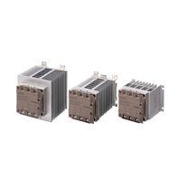
Compact, Slim-profile SSRs with Heat Sinks. Solid State Contactors for Three-phase Heaters Reduced Installation Work with DIN Track Mounting.
Related Contents
- Features
- Lineup
- Specifications
- Dimensions
- Catalog / Manual / CAD / Software
last update: September 24, 2012
Certification
UL508, CSA22.2 No.14, and EN60947-4-3
Ratings (at an Ambient Temperature of 25°C)
Operating Circuit (All Models)
| Model | Same for all models |
|---|---|
| Rated operating voltage | 12 to 24 VDC |
| Operating voltage range | 9.6 to 30 VDC |
| Rated input current (impedance) | 10 mA max. (24 VDC) |
| Must-operate voltage | 9.6 VDC max. |
| Must-release voltage | 1 VDC min. |
| Insulation method | Phototriac |
| Operation indicator | Yellow LED |
Main Circuit of Models with Built-in Heat Sinks
| Model | G3PE-
215B- 3(N) |
G3PE-
215B- 2(N) |
G3PE-
225B- 3(N) |
G3PE-
225B- 2(N) |
G3PE-
235B- 3(N) |
G3PE-
235B- 2(N) |
G3PE-
245B- 3(N) |
G3PE-
245B- 2(N) |
|---|---|---|---|---|---|---|---|---|
| Rated load voltage | 100 to 240 VAC | |||||||
| Operating voltage range | 75 to 264 VAC | |||||||
| Rated load current *1 | 15 A (at 40 ° C) | 25 A (at 40 ° C) | 35 A (at 25 ° C) | 45 A (at 25 ° C) | ||||
| Minimum load current | 0.2 A | 0.5 A | ||||||
| Inrush current resistance
(peak value) |
150 A
(60 Hz, 1 cycle) |
220 A
(60 Hz, 1 cycle) |
440 A
(60 Hz, 1 cycle) |
|||||
| Permissible I2t (reference value) | 121A2s | 260A2s | 1,260A2s | |||||
| Applicable load (resistive load:
AC1 class) *2 |
5.1 kW
(at 200 VAC) |
8.6 kW
(at 200 VAC) |
12.1 kW
(at 200 VAC) |
15.5 kW
(at 200 VAC) |
||||
| Model | G3PE-
515B- 3(N) |
G3PE-
515B- 2(N) |
G3PE-
525B- 3(N) |
G3PE-
525B- 2(N) |
G3PE-
535B- 3(N) |
G3PE-
535B- 2(N) |
G3PE-
545B- 3(N) |
G3PE-
545B- 2(N) |
|---|---|---|---|---|---|---|---|---|
| Rated load voltage | 200 to 480 VAC | |||||||
| Operating voltage range | 180 to 528 VAC | |||||||
| Rated load current *1 | 15 A (at 40 ° C) | 25 A (at 40 ° C) | 35 A (at 25 ° C) | 45 A (at 25 ° C) | ||||
| Minimum load current | 0.5 A | |||||||
| Inrush current resistance
(peak value) |
220 A
(60 Hz, 1 cycle) |
440 A
(60 Hz, 1 cycle) |
||||||
| Permissible I2t (reference value) | 260A2s | 1,260A2s | ||||||
| Applicable load (resistive load:
AC1 class) *2 |
12.5 kW
(at 480 VAC) |
20.7 kW
(at 480 VAC) |
29.0 kW
(at 480 VAC) |
37.4 kW
(at 480 VAC) |
||||
*1. The applicable load current depends on the ambient temperature. For details, refer to Load Current vs. Ambient
Temperature in Engineering Data on Data Sheet.
*2. Applicable Load
Use the following formula to calculate the maximum total capacity of a heater load for a three-phase balanced load
with delta connections.
Temperature in Engineering Data on Data Sheet.
*2. Applicable Load
Use the following formula to calculate the maximum total capacity of a heater load for a three-phase balanced load
with delta connections.
Main Circuit of Models with Externally Attached Heat Sinks
| Model | G3PE-
215B- 3H |
G3PE-
215B- 2H |
G3PE-
225B- 3HH |
G3PE-
225B- 2H |
G3PE-
235B- 3H |
G3PE-
235B- 2H |
G3PE-
245B- 3H |
G3PE-
245B- 2H |
|---|---|---|---|---|---|---|---|---|
| Rated load voltage | 100 to 240 VAC | |||||||
| Operating voltage range | 75 to 264 VAC | |||||||
| Rated load current * | 15 A (at 40 ° C) | 25 A (at 40 ° C) | 35 A (at 25 ° C) | 45 A (at 25 ° C) | ||||
| Minimum load current | 0.2 A | 0.5 A | ||||||
| Inrush current resistance
(peak value) |
150 A
(60 Hz, 1 cycle) |
220 A
(60 Hz, 1 cycle) |
440 A
(60 Hz, 1 cycle) |
|||||
| Permissible I2t (reference value) | 121A2s | 260A2s | 1,260A2s | |||||
| Applicable load (resistive load:
AC1 class) |
Refer to Engineering Data on Data Sheet. | |||||||
| Model | G3PE-
515B- 3H |
G3PE-
515B- 2H |
G3PE-
525B- 3H |
G3PE-
525B- 2H |
G3PE-
535B- 3H |
G3PE-
535B- 2H |
G3PE-
545B- 3H |
G3PE-
545B- 2H |
|---|---|---|---|---|---|---|---|---|
| Rated load voltage | 200 to 480 VAC | |||||||
| Operating voltage range | 180 to 528 VAC | |||||||
| Rated load current * | 15 A (at 40 ° C) | 25 A (at 40 ° C) | 35 A (at 25 ° C) | 45 A (at 25 ° C) | ||||
| Minimum load current | 0.5 A | |||||||
| Inrush current resistance
(peak value) |
220 A
(60 Hz, 1 cycle) |
440 A
(60 Hz, 1 cycle) |
||||||
| Permissible I2t (reference value) | 260A2s | 1,260A2s | ||||||
| Applicable load (resistive load:
AC1 class) |
Refer to Engineering Data on Data Sheet. | |||||||
* The rated load current depends on the heat sink or radiator that is mounted. It also depends on the ambient
temperature.
For details, refer to Load Current vs. Ambient Temperature in Engineering Data on Data Sheet.
temperature.
For details, refer to Load Current vs. Ambient Temperature in Engineering Data on Data Sheet.
Characteristics
Models with Built-in Heat Sinks
| Model |
G3PE- 215B- 3(N) |
G3PE- 215B- 2(N) |
G3PE- 225B- 3(N) |
G3PE- 225B- 2(N) |
G3PE- 235B- 3(N) |
G3PE- 235B- 2(N) |
G3PE- 245B- 3(N) |
G3PE- 245B- 2(N) |
|---|---|---|---|---|---|---|---|---|
| Operate time | 1/2 of load power source cycle + 1 ms max. | |||||||
| Release time | 1/2 of load power source cycle + 1 ms max. | |||||||
|
Output ON voltage drop |
1.6 V (RMS) max. | |||||||
| Leakage current * | 10 mA max. (at 200 VAC) | |||||||
|
Insulation resistance |
100 M Ω min. (at 500 VDC) | |||||||
| Dielectric strength | 2,500 VAC, 50/60 Hz for 1 min | |||||||
|
Vibration resistance |
DIN Track mounting: 10 to 55 to 10 Hz, 0.175-mm single amplitude (0.35-mm double amplitude) Screw mounting: 10 to 55 to 10 Hz, 0.375-mm single amplitude (0.75-mm double amplitude) |
|||||||
| Shock resistance | 294 m/s2 (reverse mounting: 98 m/s2) | |||||||
|
Ambient storage temperature |
- 30 to 100 ° C (with no icing or condensation) | |||||||
|
Ambient operating temperature |
- 30 to 80 ° C (with no icing or condensation) | |||||||
|
Ambient operating humidity |
45% to 85% | |||||||
| Weight | Approx. 1.25 kg | Approx. 1.45 kg |
Approx. 1.25 kg |
Approx. 1.65 kg |
Approx. 1.45 kg |
Approx. 2.0 kg |
Approx. 1.65 kg |
|
| Model |
G3PE- 515B- 3(N) |
G3PE- 515B- 2(N) |
G3PE- 525B- 3(N) |
G3PE- 525B- 2(N) |
G3PE- 535B- 3(N) |
G3PE- 535B- 2(N) |
G3PE- 545B- 3(N) |
G3PE- 545B- 2(N) |
|---|---|---|---|---|---|---|---|---|
| Operate time | 1/2 of load power source cycle + 1 ms max. | |||||||
| Release time | 1/2 of load power source cycle + 1 ms max. | |||||||
|
Output ON voltage drop |
1.8 V (RMS) max. | |||||||
| Leakage current * | 20 mA max. (at 480 VAC) | |||||||
|
Insulation resistance |
100 M Ω min. (at 500 VDC) | |||||||
| Dielectric strength | 2,500 VAC, 50/60 Hz for 1 min | |||||||
|
Vibration resistance |
DIN Track mounting: 10 to 55 to 10 Hz, 0.175-mm single amplitude (0.35-mm double amplitude) Screw mounting: 10 to 55 to 10 Hz, 0.375-mm single amplitude (0.75-mm double amplitude) |
|||||||
| Shock resistance | 294 m/s2 (reverse mounting: 98 m/s2) | |||||||
|
Ambient storage temperature |
- 30 to 100 ° C (with no icing or condensation) | |||||||
|
Ambient operating temperature |
- 30 to 80 ° C (with no icing or condensation) | |||||||
|
Ambient operating humidity |
45% to 85% | |||||||
| Weight | Approx. 1.25 kg | Approx. 1.45 kg |
Approx. 1.25 kg |
Approx. 1.65 kg |
Approx. 1.45 kg |
Approx. 2.0 kg |
Approx. 1.65 kg |
|
* The leakage current of phase S will be approximately √3 times larger if the 2-element model is used.
Models with Externally Attached Heat Sinks
| Model | G3PE-
215B- 3H |
G3PE-
215B- 2H |
G3PE-
225B- 3H |
G3PE-
225B- 2H |
G3PE-
235B- 3H |
G3PE-
235B- 2H |
G3PE-
245B- 3H |
G3PE-
245B- 2H |
|---|---|---|---|---|---|---|---|---|
| Operate time | 1/2 of load power source cycle + 1 ms max. | |||||||
| Release time | 1/2 of load power source cycle + 1 ms max. | |||||||
| Output ON voltage drop | 1.6 V (RMS) max. | |||||||
| Leakage current * | 10 mA max. (at 200 VAC) | |||||||
| Insulation resistance | 100 M Ω min. (at 500 VDC) | |||||||
| Dielectric strength | 2,500 VAC, 50/60 Hz for 1 min | |||||||
| Vibration resistance | 10 to 55 to 10 Hz, 0.375-mm single amplitude (0.75-mm double amplitude) | |||||||
| Shock resistance | Destruction: 294 m/s2 | |||||||
| Ambient storage temperature | - 30 to 100 ° C (with no icing or condensation) | |||||||
| Ambient operating temperature | - 30 to 80 ° C (with no icing or condensation) | |||||||
| Ambient operating humidity | 45% to 85% | |||||||
| Weight | Approx. 300 g | |||||||
| Model | G3PE-
515B- 3H |
G3PE-
515B- 2H |
G3PE-
525B- 3H |
G3PE-
525B- 2H |
G3PE-
535B- 3H |
G3PE-
535B- 2H |
G3PE-
545B- 3H |
G3PE-
545B- 2H |
|---|---|---|---|---|---|---|---|---|
| Operate time | 1/2 of load power source cycle + 1 ms max. | |||||||
| Release time | 1/2 of load power source cycle + 1 ms max. | |||||||
| Output ON voltage drop | 1.8 V (RMS) max. | |||||||
| Leakage current * | 20 mA max. (at 480 VAC) | |||||||
| Insulation resistance | 100 M Ω min. (at 500 VDC) | |||||||
| Dielectric strength | 2,500 VAC, 50/60 Hz for 1 min | |||||||
| Vibration resistance | 10 to 55 to 10 Hz, 0.375-mm single amplitude (0.75-mm double amplitude) | |||||||
| Shock resistance | Destruction: 294 m/s2 | |||||||
| Ambient storage temperature | - 30 to 100 ° C (with no icing or condensation) | |||||||
| Ambient operating temperature | - 30 to 80 ° C (with no icing or condensation) | |||||||
| Ambient operating humidity | 45% to 85% | |||||||
| Weight | Approx. 300 g | |||||||
* The leakage current of phase S will be approximately √3 times larger if the 2-element model is used.
Heat Sinks
| Model | Weight |
|---|---|
| Y92B-P50 | Approx. 450 g |
| Y92B-P100 | Approx. 450 g |
| Y92B-P150 | Approx. 600 g |
| Y92B-P200 | Approx. 850 g |
| Y92B-P250 | Approx. 1,200 g |
last update: September 24, 2012