K8DT-VS
Single-phase Voltage Relay
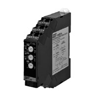
Our Value Design Products Increase the Value of Your Control Panels. Detect abnormal voltages applies to equipment to protect against equipment failure. Use in either overvoltage or undervoltage mode.
Related Contents
- Features
- Lineup
- Specifications
- Dimensions
- Catalog / Manual / CAD / Software
last update: March 1, 2019
Input Range
| Model | Range * | Connection terminal | Setting range | Input impedance | Overload capacity |
|---|---|---|---|---|---|
| K8DT-VS2[][] | 0 to 10 V AC/DC | V1-COM | 1 to 10 V AC/DC | Approx. 120 kΩ | Continuous input at
115% of maximum input 10 s at 125% (up to 600 VAC) |
| 0 to 30 V AC/DC | V2-COM | 3 to 30 V AC/DC | Approx. 320 kΩ | ||
| 0 to 150 V AC/DC | V3-COM | 15 to 150 V AC/DC | Approx. 1.6 MΩ | ||
| K8DT-VS3[][] | 0 to 200 V AC/DC | V1-COM | 20 to 200 V AC/DC | Approx. 1.2 MΩ | |
| 0 to 300 V AC/DC | V2-COM | 30 to 300 V AC/DC | Approx. 1.7 MΩ | ||
| 0 to 600 V AC/DC | V3-COM | 60 to 600 V AC/DC | Approx. 3.1 MΩ |
* The range is selected using connected terminals.
Ratings
| Power supply voltage | K8DT-VS[][]D: 24 VAC 50/60Hz, 24 VDC
K8DT-VS[][]A: 100 to 240 VAC 50/60Hz |
|---|---|
| Power consumption | 24 VAC/DC: 1.8 VA/1 W max.
100 to 240 VAC: 2.5 VA max. |
| Rated insulation
voltage |
600 VAC |
| Operating value setting
range (SV) |
10% to 100% of maximum setting range
K8DT-VS2: 1 to 10 V AC/DC 3 to 30 V AC/DC 15 to 150 V AC/DC K8DT-VS3: 20 to 200 V AC/DC 30 to 300 V AC/DC 60 to 600 V AC/DC |
| Operating value | 100% operation at set value |
| Reset value setting range (HYS) | 5% to 50% of operating value |
| Reset method | Manual reset/automatic reset (switchable)
Note:Manual reset: Turn OFF power supply for 1 s or longer. |
| Operating time setting
range (T) |
0.1 to 30 s |
| Power ON lock time | 1 s or 5 s (Switched using DIP switch.) |
| Indicators | Power (PWR): Green, Relay output (RY): Yellow,
Alarm outputs (ALM): Red |
| Input impedance | Refer to Input Range on catalog. |
| Output form | Relay Output: SPDT contact
Transistor Output: 1 Switchable between normally open and normally closed with a DIP switch setting. |
| Output relay ratings | Rated load
5 A at 250 VAC (Resistive load) 5 A at 30 VDC (Resistive load) 1 A at 250 VAC (Inductive load) 0.2 A at 48 VDC (Inductive load) Minimum load: 5 VDC, 10 mA (reference values) Mechanical life: 10 million operations min. Electrical life: 5 A at 250 VAC or 30 VDC: 50,000 operations 3 A at 250 VAC or 30 VDC: 100,000 operations |
| Transistor output
ratings |
Rated voltage: 24 VDC (maximum voltage: 26.4 VDC)
Maximum current: 50 mA DC |
| Ambient operating
temperature |
-20 to 60°C (with no condensation or icing) |
| Storage temperature | -25 to 65°C (with no condensation or icing) |
| Ambient operating
humidity |
25% to 85% RH (with no condensation) |
| Storage humidity | 25% to 85% RH (with no condensation) |
| Altitude | 2,000 m max. |
| Applicable wires | Stranded wires, solid wires, or ferrules |
| Applicable wire size | 0.25 to 1.5 mm2(AWG24 to AWG16) |
| Wire insertion force | 8 N max. for AWG20 wire |
| Screwdriver insertion force | 15 N max. |
| Wire stripping length | 8 mm |
| Ferrule length | 8 mm |
| Recommended flat-blade screwdriver | XW4Z-00B (Omron)
SZF 0.4 × 2.5 (Phoenix Contact) 210-719 (Wago) SDI 0.4 × 2.5 × 75 (Weidmuller) |
| Current capacity | 10 A (per pole) |
| Number of insertions | 50 times |
| Case color | N1.5 |
| Case material | PC, UL 94 V-0 |
| Weight | Approx. 100 g |
| Mounting | Mounts to DIN Track, or screw mounting |
| Dimensions | 17.5 × 90 × 90 mm (W×H×D) |
Specifications
| Allowable operating
voltage range |
85% to 110% of rated power supply voltage | |
|---|---|---|
| Allowable operating
frequency range |
50/60 Hz ±5 Hz | |
| Input frequency range | 40 to 500 Hz | |
| Overload capacity | Continuous input at 115% of maximum input, 10 s at 125% (up to 600 VAC). | |
| Repeat
accuracy |
Operating
value |
±0.5% full scale (at 25°C and 65% humidity, rated power supply voltage) |
| Operating
time |
±50 ms (at 25°C and 65% humidity, rated power supply voltage) | |
| Applicable
standards |
Conforming
standards |
EN 60947-5-1
Installation environment (pollution level 2, Overvoltage category III) |
| EMC | EN 60947-5-1 | |
| Safety
standards |
UL 60947-5-1 (Listing),
Korean Radio Waves Act (Act 10564), CCC (GB/T 14048.5) |
|
| Insulation resistance | 20 MΩmin.
Between external terminals and case Between power supply terminals and input terminals Between power supply terminals and output terminals Between input terminals and output terminals |
|
| Dielectric strength | 2,000 VAC for one minute
Between external terminals and case Between power supply terminals and input terminals Between power supply terminals and output terminals Between input terminals and output terminals |
|
| Impulse withstand
voltage |
6 kV (between live terminals and exposed, non-charged metal parts) | |
| Noise immunity | Square-wave noise of 1-μs/100-ns pulse width with 1-ns rise time
100 to 240 VAC: 1,500 V power supply terminal common/normal mode 24 VAC: 1,500 V power supply terminal common/normal mode 24 VDC: 480 V power supply terminal common |
|
| Vibration resistance | Frequency: 10 to 55 Hz, 0.35-mm single amplitude
10 sweeps of 5 min each in X,Y, and Z directions |
|
| Shock resistance | 100 m/s2, 3 times each in 6 directions along 3 axes | |
| Degree of protection | Terminals: IP20 | |
last update: March 1, 2019