KM-N3-FLK
Power Monitor
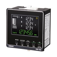
Global Power Monitor for On-panel Installation
Related Contents

- Features
- Lineup
- Specifications
- Dimensions
- Catalog / Manual / CAD / Software
last update: February 20, 2023
Ratings (Power Monitor)
| Model | KM-N3-FLK | |
|---|---|---|
| Applicable phase wiring methods | Single-phase two-wire, single-phase three-wire, three-phase three-wire,
and three-phase four-wire |
|
| Number of measured circuits | Single-phase two-wire: 4 circuits max., Single-phase three-wire or three-
phase three-wire: 2 circuits max., Three-phase four-wire: 1 circuit |
|
| Power supply voltage (operating frequency) | 100 to 240 VAC (50/60 Hz) | |
| Power supply allowable voltage range | 85% to 110% of rated power supply voltage | |
| Power consumption | 7 VA max. | |
| Input | Rated input voltages | Single-phase, 2-wire: 100 to 277 VAC
Single-phase, 3-wire: 100 to 240 VAC (L-N), 200 to 480 VAC (L-L) Three-phase, 3-wire: 173 to 277 VAC (L-L) Three-phase, 4-wire (earthed neutral): 100 to 277 VAC (L-N), 173 to 480 VAC (L-L) Three-phase, 4-wire (unearthed neutral): 100 to 120 VAC (L-N), 173 to 208 VAC (L-L) |
| Allowable supply voltage range | 85% to 115% of rated power supply voltage | |
| Connectable CTs | General-purpose CT with a rated secondary current of 1 A or 5 A * | |
| Maximum CT secondary current | 6 A | |
| Rated input frequency | 50/60 Hz | |
| Ambient operating temperature | -25 to 55°C (with no condensation or icing) | |
| Ambient operating humidity | 25% to 85% | |
| Storage temperature | -25 to 85°C (with no condensation or icing) | |
| Storage humidity | 25% to 85% | |
| Operating altitude | 2,000 m max. | |
| Installation environment | Overvoltage category II, measurement category II, pollution degree 2 | |
| Electromagnetic environment | Industrial electromagnetic environment (EN/IEC 61326-1 Table 2) | |
| Compliant standards | EN 61010-2-030, EN 61326-1, and UL 61010-1 | |
* The KM-series CTs (the KM20-CTF or KM-NCT Series) cannot be used. Use general-purpose CTs with a secondary-side output of 1 A or 5 A.
Split Type Current Transformer (CT) (CE marking compliant KM-N2/N3 dedicated products *)
| Item | KM-NCT-E100A | KM-NCT-E250A | KM-NCT-E500A |
|---|---|---|---|
| Rated primary current: In | 100 A | 250 A | 500 A |
| Rated secondary current: Is | 1 A | ||
| Rated frequency | 50/60 Hz | ||
| Cable Length | Please refer to Writing to KM-NCT-E[][][]A | ||
| Rated load | 1 VA | ||
| Insulation resistance | 100 MΩ min. (at 500 VDC mega) between core and all output terminals | ||
| Dielectric strength voltage | 2300 VAC, 1 minute between core and all output terminals. | ||
| Weight | Approx. 170 g | Approx. 175 g | Approx. 290 g |
| Maximum wire diameter | 24 dia. | 24 dia. | 36 dia. |
| Operating temperature and humidity range | -20 to 55 °C, relative humidity: 85% max. with no condensation | ||
| Storage temperature and humidity range | -30 to 90 °C, relative humidity: 85% max. with no condensation | ||
| Applicable standards * | EN61010-1, EN61010-2-030, EN61326-1 | ||
| Installation environment | Overvoltage category and measurement category: II, Pollution level: 2 | ||
* The KM-NCT-E conforms to the standards shown above ONLY when it is used with a power monitor KM-N2-FLK or KM-N3-FLK to which it is attached. Use of the KM-NCT-E without a power monitor does not conform to these standards.
Wiring to KM-NCT-E[][][]A
• For wiring of the output terminal of CT, use AWG18-14 electric wire (with a cross-section of 0.75-2.0mm2) and Y-shape terminal compatible with the M3 screw.
• The recommended torque for screwing the M3 screws onto the output terminal is 0.3 N·m. Make sure the Y terminal is pushed all the way in and tightened firmly. After fixing the wiring, confirm that the wire is fixed securely.
• The guideline of the maximum wiring length between KM-N2-FLK or KM-N3-FLK and KM-NCT-E is as follows.
The longer the wire length, the larger the measurement error using the KM-NCT-E becomes.
• The limit of the wiring length can also be calculated by the following formula. Calculate the wiring length limit according to the conductor resistivity of the wiring and keep the wiring length below the limit.
• The limits of the wiring length shown below are for reference only. They do not guarantee proper use.
| Wiring diameter | Guideline for wiring length limit |
|---|---|
| 0.75 mm2 (AWG18 equivalent) | 15 m |
| 2.0 mm2 (AWG14 equivalent) | 43 m |
Wiring extension limit value (one-way) (m)= 0.475/conductor resistivity (Ω/m)
Note: Select a CT cable that does not exceed the rated load of 1 VA.
Performance (Power Monitor)
| Model | KM-N3-FLK | |
|---|---|---|
| Measured items | Total power consumption (active, regenerative, and reactive), power (active and
reactive), current, voltage, power factor, and frequency |
|
| Meas-
urement specifi- cations |
Active power | 0.5% (IEC 62053-22 class 0.5S * |
| Reactive power | 2% (IEC 62053-23 class 2) * | |
| Sampling cycle | 80 ms for 50 Hz and 66.7 ms for 60 Hz | |
| Insulation resistance | (1) Between all electrical circuits and the case: 20 MΩ min. (at 500 VDC)
(2) Between all power supply and voltage inputs and all communications and pulse output terminals: 20 MΩ max. (at 500 VDC) |
|
| Dielectric strength | (1) Between all electrical circuits and the case: 1,400 VAC for 1 min
(2) Between all voltage and current inputs and all communications and pulse output terminals: 1,400 VAC for 1 min |
|
| Vibration resistance | Single amplitude: 0.1 mm, Acceleration: 15 m/s2, Frequency: 10 to 150 Hz, 10
sweeps for 8 min each along three axes |
|
| Shock resistance | 150 m/s2, 3 times each in 6 directions (up/down, left/right, forward/backward) | |
| Indications and operation method | LCD indications and operation buttons | |
| Weight | Approx. 350 g (Power Monitor only) | |
| Degree of protection | Front: IP65, Rear case: IP20, Terminal: IP00 | |
| Pulse
output |
Number of outputs | Number of outputs: 4 (photoMOS relay outputs)
Used for the total power consumption pulse output. |
| Output capacity | 50 mA at 40 VDC
ON residual voltage: 1.5 V max. (for output current of 50 mA) OFF leakage current: 0.1 mA max. |
|
| Output unit | Output unit: 1, 10, 100, 1k, 5k, 10k, 50k, or 100k (wh)
Pulse ON time: 500 ms (Cannot be changed.) |
|
| Commu-
nications interface |
Communications method | RS-485 (2-wire half-duplex with start-stop synchronization) |
| Communications protocol | Modbus (RTU): Binary. CompoWay/F: ASCII | |
| Baud rate | 1.2, 2.4, 4.8, 9.6, 19.2, or 38.4 kbps | |
| Data length | Data length: 7 or 8 bits
Stop bits: 1 or 2 bits Vertical parity: Even, odd, or none |
|
| Maximum transmission
distance |
1,200 m | |
| Maximum number of
connected Power Monitors |
Modbus: 99, CompoWay/F: 31
If you measure more than one circuit with one Power Monitor, the number of circuits is treated as the number of connected Power Monitors. |
|
| Dimensions (H×W×D) | 96 × 96 × 64 mm (excluding protrusions) | |
| Installation method | On-panel installation | |
| Accessories | Instruction Manual and Compliance Sheet, Mounting adapter and waterproof
packing |
|
* The error of the CT or VT is not included. IEC 62053 is an international standard for power metering.
last update: February 20, 2023