NA Series(-V2)
Programmable Terminal
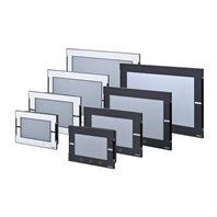
The Omron Sysmac HMI enables faster, more efficient control and monitoring - and a more natural, proactive relationship between operator and machine. Wide screen models: 7, 9, 12 and 15 inches
Related Contents
 Application Solutions
- Features
- Lineup
- Specifications
- Dimensions
- Catalog / Manual / CAD / Software
last update: October 1, 2026
Performance Specifications
Display
| Item | Specification | ||||
|---|---|---|---|---|---|
| NA5-15W[][][][]-V2 | NA5-12W[][][][]-V2 | NA5-9W[][][][]-V2 | NA5-7W[][][][]-V2 | ||
| Display panel
*1 |
Display device | TFT LCD | |||
| Screen size | 15.4 inches | 12.1 inches | 9.0 inches | 7.0 inches | |
| Resolution | 1,280 × 800 dots (horizontal × vertical) | 800 × 480 dots (horizontal × vertical) | |||
| Colors | 16,770,000 colors (24 bit full colors) | ||||
| Effective
display area |
331 × 207 mm
(horizontal × vertical) |
261 × 163 mm
(horizontal × vertical) |
197 × 118 mm
(horizontal × vertical) |
152 × 91 mm
(horizontal × vertical) |
|
| View angles | Left: 60°, Right: 60°, Top: 60°, Bottom: 60° | ||||
| Backlight *2 | Life | 50,000 hours min. *3 | |||
| Brightness
adjustment |
200 levels | ||||
| Type | LED | ||||
| Front panel
indicators *4 |
RUN | Lit green: Normal operation Lit red: Error | |||
*1. There may be some defective pixels in the display. This is not a fault as long as the numbers of defective light and dark pixels fall within the following standard ranges.
| Model | Standard range |
|---|---|
| NA5-15W[][][][]-V2
NA5-12W[][][][]-V2 NA5-9W[][][][]-V2 NA5-7W[][][][]-V2 |
Number of light and dark pixels: 10 or less.
(There must not be 3 consecutive light/dark pixels.) |
*2. The backlight can be replaced at an OMRON maintenance base.
*3. This is the estimated time before brightness is reduced by half at room temperature and humidity. The life expectancy is drastically shortened if Programmable Terminal is used at high temperatures.
*4. The brightness of the front panel indicators is also adjustable when you adjust the brightness of the backlight.
Operation
| Item | Specification | |||
|---|---|---|---|---|
| NA5-15W[][][][]-V2 | NA5-12W[][][][]-V2 | NA5-9W[][][][]-V2 | NA5-7W[][][][]-V2 | |
| Touch panel | Method: Analog resistive membrane type | |||
| Life: 1,000,000 operations | ||||
| Function keys *1 | 3 inputs (capacitance inputs) | |||
*1. Each function key has blue indicator. The brightness of the function key indicators is also adjustable when you adjust the brightness of the backlight.
Data Capacity
| Item | Specification | |||
|---|---|---|---|---|
| NA5-15W[][][][]-V2 | NA5-12W[][][][]-V2 | NA5-9W[][][][]-V2 | NA5-7W[][][][]-V2 | |
| User data capacity | 256 MB | |||
External Interfaces
| Item | Specifications (Same for all models.) | |
|---|---|---|
| Ethernet
ports |
Applications | Port 1: Connecting to anything other than the Sysmac Studio, e.g., device
connections and VNC clients Port 2: Connecting to the Sysmac Studio in addition to the applications of port 1. |
| Number of ports | 2 ports | |
| Compliant standards | IEEE 802.3i (10BASE-T), IEEE 802.3u (100BASE-TX), and IEEE 802.3ab
(1000Base-T) |
|
| Transmission media | Shielded twisted-pair (STP) cable: Category 5, 5e, or higher | |
| Transmission distance | 100 m | |
| Connector | RJ-45 8P8C modular connector | |
| USB Type-A
ports *1 *2 |
Applications | USB Memory Device, keyboard, or mouse |
| Number of ports | 2 ports | |
| Compliant standards | USB 2.0 | |
| Transmission distance | 5 m max. | |
| Connector | Type-A connector | |
| USB Type-B
port *1 |
Applications | Sysmac Studio connection |
| Number of ports | 1 port | |
| Compliant standards | USB 2.0 | |
| Transmission distance | 5 m max. | |
| Connector | Type-B connector | |
| Serial port | Applications | Device Connection |
| Number of ports | 1 port | |
| Compliant standards | RS-232C | |
| Transmission distance | 15 m max. | |
| Connector | D-DUB 9-pin female connector | |
| SD Memory
Card slot |
Applications | To transfer or store the project or to store log data. |
| Number of slots | 1 slot | |
| Compliant standards | SD/SDHC | |
*1. Connection to all USB 2.0-compliant devices is not guaranteed.
*2. Use a USB memory for temporary applications such as transferring data.
General Specifications
| Item | Specification | |||
|---|---|---|---|---|
| NA5-15W[][][][]-V2 | NA5-12W[][][][]-V2 | NA5-9W[][][][]-V2 | NA5-7W[][][][]-V2 | |
| Rated supply
voltage |
24 VDC | |||
| Allowable power
supply voltage range |
19.2 to 28.8 VDC (24 VDC ±20%) | |||
| Allowable
momentary power interruption time |
Operation for momentary power interruption is not specified. | |||
| Power
consumption |
29 W max. | 28 W max. | 23 W max. | 19 W max. |
| Inrush current *1 | During a cold start at 24 VDC input and room temperature 4.0 A max. 30 μs max. *2 | |||
| Ambient operating
temperature |
0 to 50°C *3 *4 | |||
| Ambient storage
temperature |
-20 to +60°C *5 | |||
| Ambient operating
humidity |
10 to 90% *4
Must be no condensation. |
|||
| Atmosphere | Must be free from corrosive gases. | |||
| Pollution degree | 2 or less: Meets IEC 61010-2-201. | |||
| Noise immunity | 2 kV on power supply line (Conforms to IEC 61000-4-4.) | |||
| Vibration resistance
(during operation) |
5 to 8.4 Hz with 3.5 mm half amplitude and 8.4 to 150 Hz with 9.8 m/s2 for 100 minutes
each in X,Y, and Z directions (Time coefficient of 10 minutes × coefficient factor of 10 = total time of 100 min.) |
|||
| Shock resistance
(during operation) |
Conforms to IEC 60028-2-27.
147 m/s2 3 times each in X, Y, and Z directions |
|||
| Dimensions | 414 × 287 × 69 mm
(W × H × D) |
333 × 240 × 69 mm
(W × H × D) |
283 × 185 × 69 mm
(W × H × D) |
220 × 160 × 69 mm
(W × H × D) |
| Panel cutout
dimensions |
392 +1,0 ×
268 +1,0 mm (horizontal × vertical) Panel thickness: 1.6 to 6.0 mm *6 |
310 +1,0 ×
221 +1,0 mm (horizontal × vertical) Panel thickness: 1.6 to 6.0 mm *6 |
261 +1,0 ×
166 +1,0 mm (horizontal × vertical) Panel thickness: 1.6 to 6.0 mm *6 |
197 +0.5,0 ×
141 +0.5,0 mm (horizontal × vertical) Panel thickness: 1.6 to 6.0 mm *6 |
| Weight | 2.6 kg max. | 1.9 kg max. | 1.3 kg max. | 1.0 kg max. |
| Degree of
protection |
IP65, UL Type 4X *6 (Front-panel controls)
To reinstall the NA Unit in a panel, contact your OMRON representative for replacement of the rubber packing. |
|||
| Case | Plastic | |||
| Battery life *7 | Battery life: 5 years at 25°C
The RTC will be backed up for 5 days after the battery runs low. The RTC will be backed up by a super capacitor for 5 minutes after removing the old battery. (This assumes that the power is first turned ON for at least 5 minutes and then turned OFF.) |
|||
| RTC | Ambient temperature 25°C: Maximum error of ±90 seconds per month | |||
| International
standards *8 |
UL61010-2-201/CSA C22.2 NO.61010-2-201: 14 *9
EMC Regulations (2004/108/EC) EN61131-2: 2007 Shipbuilding standards NK IP65, UL Type 4X *6 (Front-panel controls) UL121201, 9th Edition/CSA C22.2 NO.213-2017 UKCA KC KN61131-2 2018 RCM EN61000-6-4: 2007+A1: 2011 |
|||
*1. The inrush current value may vary depending on the conditions. When selecting the fuse, circuit breaker, and external power supply unit, carefully think about the operating conditions and select devices with sufficientmargins for the characteristics and capacity.
*2. The inrush current is dependent on the input voltage. This current is approximately 5.5 A at 28.8 VDC.
*3. The ambient operating temperature is subject to the following restrictions, depending on the mounting angle.
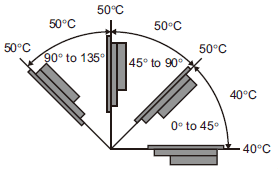
• The ambient operating temperature is 0° to 40°C when the mounting angle is 0° or more and less than 45° to the horizontal.
• The ambient operating temperature is 0° to 50°C when the mounting angle is 45° or more and 90° or less to the horizontal.
• The ambient operating temperature is 0° to 50°C when the mounting angle is 90° or more and 135° or less to the horizontal.
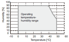
*4. Use the Programmable Terminal within the following temperature and humidity ranges.
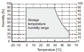
*5. Store the Programmable Terminal within the following temperature and humidity ranges.
*6. To conform to UL Type 4X standards, you may have to use the NA-[]WATW01 High-pressure Waterproof Attachment (sold separately).
When the NA-[]WATW01 High-pressure Waterproof Attachment is used, the panel thickness is between 1.6 to 4.5 mm.
*7. The battery is sold separately. Even when a battery is not installed, the RTC can be backed up by a built-in capacitor for a maximum of 10 days.
*8. Check with your OMRON representative or refer to the following OMRON website for the latest information on the applicable standards for each model: www.ia.omron.com.
*9. Use power supply Class 2 to conform to UL Standards.
Version Information
NA series and Programming Devices
| NA series | Corresponding unit versions/version | ||
|---|---|---|---|
| Model | NA system version | NJ/NX/NY-series Controller
NX701-[][][][] NY512-[][][][] NX502-[][][][] NY532-[][][][] NX102-[][][][] NJ501-[][][][] NX1P2-[][][][] NJ301-[][][][] NX-CSG320 NJ101-[][][][] |
Sysmac studio |
| NA5-[][][][][][]-V2 | 1.18 or later | NX502: 1.60 or later | 1.64 or higher |
| NX-CSG320: 1.00 or later | |||
| NX102: 1.30 or later | |||
| NX1P2: 1.13 or later
NY512: 1.12 or later NY532: 1.12 or later NX701: 1.10 or later NJ101: 1.10 or later NJ501: 1.01 or later NJ501 Database Connection: 1.05 or later NJ301: 1.01 or later |
|||
Supported Devices
NA5-[][][][][][]-V2
| Manufacturer | Models | Connection method | Communications driver |
|---|---|---|---|
| OMRON | NX102-[][][][]
NX1P2-[][][][] NX502-[][][][] NX701-[][][][] NJ501-[][][][] NJ301-[][][][] NJ101-[][][][] NY512-[][][][] NY532-[][][][] NX-CSG320 |
Built-in EtherNet/IP port | Ethernet |
| NX502-[][][][] | NX-EIP201 | ||
| CJ2H-CPU64/65/66/67/68-EIP
CJ2M-CPU31/32/33/34/35 CJ3M-CPU31/32/33/34/35 |
Built-in EtherNet/IP port | CIP Ethernet | |
| CJ2H-CPU64/65/66/67/68
CJ2M-CPU11/12/13/14/15 CJ3M-CPU11/12/13/14/15 |
CJ1W-EIP21S | ||
| CJ2H-CPU64/65/66/67/68-EIP
CJ2M-CPU31/32/33/34/35 CJ3M-CPU31/32/33/34/35 |
CJ1W-EIP21 | ||
| CJ2H-CPU64/65/66/67/68-EIP
CJ2M-CPU31/32/33/34/35 CJ3M-CPU31/32/33/34/35 |
Built-in EtherNet/IP port | FINS Ethernet | |
| CJ1H-CPU65H/66H/67H
CJ1H-CPU65H/66H/67H-R CJ1G-CPU42H/43H/44H/45H CJ1M-CPU11/12/13/21/22/23 CJ2H-CPU64/65/66/67/68(-EIP) CJ2M-CPU11/12/13/14/15 CJ2M-CPU31/32/33/34/35 CJ3M-CPU31/32/33/34/35 |
CJ1W-ETN21
CJ1W-EIP21 |
||
| CJ2H-CPU64/65/66/67/68
CJ2M-CPU11/12/13/14/15 CJ3M-CPU11/12/13/14/15 |
CJ1W-EIP21S | ||
| CS1G-CPU42H/43H/44H/45H
CS1H-CPU63H/64H/65H/66H/67H |
CS1W-ETN21
CS1W-EIP21 |
||
| CS1G-CPU43H/44H/45H
CS1H-CPU63H/64H/65H/66H/67H |
CS1W-EIP21S | ||
| CS1D-CPU65H/67H/67HA/68HA/44SA/67SA | CS1W-ETN21
CS1D-ETN21D CS1W-EIP21 CS1W-EIP21S |
||
| CP1L-EL[][][][]-[]
CP1L-EM[][][][] CP2E-N[][]D[]-[] |
Built-in Ethernet port | ||
| CP1H-[][][][][]-[]
CP1L-L[][][][]-[] |
CP1W-CIF41 | ||
| CK3E-1[]10
CK3M-CPU1[]1 |
Built-in Ethernet port | Modbus/TCP | |
| CS1G-CPU42H/43H/44H/45H
CS1H-CPU63H/64H/65H/66H/67H CS1D-CPU65H/67H/67HA/68HA/44SA/57SA |
Built-in RS-232C port
CS1W-SCB21-V1 CS1W-SCB41-V1 CS1W-SCU21-V1 CS1W-SCU31-V1 |
Host Link | |
| CJ2H-CPU64/65/66/67/68(-EIP)
CJ2M-CPU11/12/13/14/15/31/32/33/34/35 CJ3M-CPU11/12/13/14/15/31/32/33/34/35 |
Built-in RS-232C port
CJ1W-SCU22 CJ1W-SCU32 CJ1W-SCU42 |
||
| CP1L-[][][][][]-[]
CP1H-[][][][][]-[] CJ2M-CPU31/32/33/34/35 CJ3M-CPU31/32/33/34/35 |
CP1W-CIF01
CP1W-CIF11 CP1W-CIF12-V1 |
||
| CP2E-E[][]D[]-[]
CP2E-S[][]D[]-[] |
Built-in RS-232C port |
Note: 1. Including models no longer available to order.
NA-RTLD[][]
| Manufacturer | Models | Connection method | Communications driver |
|---|---|---|---|
| OMRON | NX102-[][][][]
NX1P2-[][][][] NX502-[][][][] NX701-[][][][] NJ501-[][][][] NJ301-[][][][] NJ101-[][][][] NY512-[][][][] NY532-[][][][] NX-CSG320 |
Built-in EtherNet/IP port | Ethernet |
| NX502-[][][][] | NX-EIP201 |
last update: October 1, 2026
 Top of page