Discontinued On Mar. 2023
H7AN
Digital Counter (DIN 72 × 72)
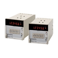
A DIN 72 x 72 mm Best-selling Counter
* Information in this page is a reference that you created on the basis of information in the product catalog before the end of production, may be different from the current situation, such as goods for / supported standards options / price / features of the product. Before using, please check the compatibility and safety system.
Related Contents
- Features
- Lineup
- Specifications
- Dimensions
- Catalog / Manual / CAD / Software
last update: July 5, 2019
Preset Counters
Incrementing/Decrementing Counters
| Operating method | Incrementing and decrementing (selectable with DIP switch) | |||
|---|---|---|---|---|
| Mounting method | Flush mounting | |||
| Operation modes | N, F, C, R, K, P, Q (selectable with rotary DIP switch) | |||
| Input signal method
(Count and reset inputs) |
Contact and transistor input voltage (H and L) | |||
| Control output | 1-stage counters: Contact (SPDT) and transistor output (H and L output switchable)
2-stage counters: Contact (SPST-NO) and transistor output (H and L output switchable) |
|||
| Set value read | Continuous mode | |||
| Memory backup | No | Yes/No (Selectable using DIP switch) | ||
| Display | Yes (10-mm high 7-segment LED, Up
indicator) |
Yes (10-mm high 7-segment LED, Up
indicator) |
||
| Models | 2 digits | 1 stage | H7AN-2D | H7AN-2DM |
| 4 digits | 1 stage | H7AN-4D | H7AN-4DM | |
| 2 stages | H7AN-W4D | H7AN-W4DM | ||
Reversible Counters
| Operating method | Reversible (selectable with rotary DIP switch) between 0 and the set value
Incrementing/decrementing A/D (command inputs) Incrementing/decrementing B/E (individual inputs) Incrementing/decrementing C/F (phase difference inputs) |
|||
|---|---|---|---|---|
| Mounting method | Flush mounting | |||
| Operation modes | N, F, C, R, K, P, Q (selectable with rotary DIP switch) | |||
| Input signal method
(Count, reset input) |
Contact and transistor input voltage (H and L) | |||
| Control output | 1-stage counters: Contact (SPDT) and transistor output (H and L output switchable)
2-stage counters: Contact (SPST-NO) and transistor output (H and L output switchable) |
|||
| Set value read | Continuous mode | |||
| Memory backup | No | Yes/No (Selectable using DIP switch) | ||
| Display | Yes (10-mm high 7-segment LED, Up indicator) | |||
| Models | 2 digits | 1 stage | H7AN-E2D | H7AN-E2DM |
| 4 digits | 1 stage | H7AN-E4D | H7AN-E4DM | |
| 2 stages | H7AN-WE4D | H7AN-WE4DM | ||
Incrementing, Decrementing, and Reversible Counters
| Operating method | Incrementing, decrementing, and reversible (UP/DOWN A to F) (selectable with rotary
DIP switch) |
|||
|---|---|---|---|---|
| Mounting method | Flush mounting | |||
| Operation modes | N, F, C, R, K, P, Q (selectable with rotary DIP switch) | |||
| Input signal method
(Count, reset input) |
Contact and transistor input voltage (H and L) | |||
| Control output | 1-stage counters: Contact (SPDT) and transistor output (H and L output switchable)
2-stage counters: Contact (SPST-NO) and transistor output (H and L output switchable) |
|||
| Set value read | Continuous mode, Reset mode (selectable) | |||
| Memory backup | No | Yes/No (Selectable using DIP switch) | ||
| Display | Yes (8-mm high 7-segment LED, Up indicator) | |||
| Models | 6 digits | 1 stage | H7AN-R6D | H7AN-R6DM |
| 2 stage | H7AN-RW6D | H7AN-RW6DM | ||
| 8 digits | 1 stages | H7AN-R8D | H7AN-R8DM | |
Totalizing Counters
Incrementing/Decrementing Counters
| Operating method | Incrementing and decrementing (selectable with DIP switch) | ||
|---|---|---|---|
| Mounting method | Flush mounting | ||
| Input signal method (Count, reset input) | Contact and transistor input voltage (H and L) | ||
| Memory backup | No | Yes/No (Selectable using DIP switch) | |
| Display | Yes (10-mm high 7-segment LED) | ||
| Models | 4 digits | H7AN-T4 | H7AN-T4M |
Reversible Counters
| Operating method | Reversible (selectable with rotary DIP switch) between 0 and the full scale
Incrementing/decrementing A/D (command inputs) Incrementing/decrementing B/E (individual inputs) Incrementing/decrementing C/F (phase difference inputs) |
|
|---|---|---|
| Mounting method | Flush mounting | |
| Input signal method
(Count, reset input) |
Contact and transistor input voltage (H and L) | |
| Memory backup | Yes/No (Selectable using DIP switch) | |
| Display | Yes (10-mm high 7-segment LED) | |
| Models | 4 digits | H7AN-ET4M |
Incrementing, Decrementing, and Reversible Counters
| Operating method | Incrementing, decrementing, and reversible (UP/DOWN A to F) | ||
|---|---|---|---|
| Mounting method | Flush mounting | ||
| Input signal method (Count, reset input) | Contact and transistor input voltage (H and L) | ||
| Memory backup | No | Yes/No (Selectable using DIP switch) | |
| Display | Yes (8-mm high 7-segment LED) | ||
| Models | 6 digits | H7AN-RT6 | H7AN-RT6M |
| 8 digits | --- | H7AN-RT8M | |
Ratings
| Rated supply voltage | 100 to 240 VAC, 50/60 Hz (common use); 12 to 24, 48, 100 VDC *1 |
|---|---|
| Operating voltage range | 85% to 110% of rated voltage |
| Power consumption | Approx. 10 VA (240 VAC at 50 Hz); Approx. 5 W (at 24 VDC) *2 |
| Max. counting speed of CP1 and
CP2 |
2-digit counters: 30 Hz
4-digit counters: 30 Hz or 5 kHz 6- or 8-digit counters: 30 Hz or 5 kHz Minimum signal width (with ON/OFF ratio of 1:1): 30 Hz: 16.7 ms, 5 kHz: 0.1 ms H: 4.5 to 30 VDC, L: 0 to 2 VDC |
| Reset | Power supply reset (except for H7AN Counter with suffix "-M"):
Minimum power-OFF time: 0.5 s with a reset time of 0.05 s after power-ON. External, manual, reset signal time: 0.02 s Reset time after completion of reset signal: 0.05 s Automatic reset *3 |
| Control output | Contacts: 3 A at 250 VAC, resistive load (cosφ = 1)
No-contacts: 100 mA max. at 30 VDC max., open collector |
| Min. applicable load | 10 mA at 5 VDC (p level reference value) |
| External power supply | 80 mA, 12 VDC ±10% (contains 5% ripple max.) |
| Ambient temperature | Operating: -10°C to 55°C (with no icing)
Storage: -25°C to 65°C (with no icing) |
| Ambient humidity | 35% to 85% |
| Case color | Light gray (Munsell 5Y7/1) |
*1. The ripple is 20% max.
*2. There is an inrush current of 14 A at 240 VAC for approximately 0.6 ms, 15 A at 12 to 24 VDC for 2 ms, 5 A at 48
VDC for 3 ms, or 8 A at 100 VDC for 2 ms immediately after power-ON.
*3. Only preset counters can be automatically reset.
*2. There is an inrush current of 14 A at 240 VAC for approximately 0.6 ms, 15 A at 12 to 24 VDC for 2 ms, 5 A at 48
VDC for 3 ms, or 8 A at 100 VDC for 2 ms immediately after power-ON.
*3. Only preset counters can be automatically reset.
Characteristics
| Insulation resistance | 100 MW min. (at 500 VDC) (between current-carrying terminal and exposed non-current-
carrying metal parts, and between non-continuous contacts) |
|---|---|
| Dielectric strength | 2,000 VAC, 50/60 Hz for 1 min (between current-carrying terminal and exposed non-
current carrying metal parts) 750 VAC, 50/60 Hz for 1 min (between non-continuous contacts) |
| Impulse withstand voltage | 6 kV (between power terminals), 6 kV (between current-carrying terminal and exposed
non-current-carrying metal parts) |
| Noise immunity | ±2 kV between power terminals (±480 V for models with 12 to 24 VDC)
±500 V between input terminals Square-wave noise by noise simulator (pulse width: 100 ns, 1-ns rise) |
| Vibration resistance | Destruction:10 to 55 Hz, 0.75-mm double amplitude
Malfunction:10 to 55 Hz, 0.5-mm double amplitude |
| Shock resistance | Destruction: 300 m/s2
Malfunction: 100 m/s2 |
| Life expectancy | Mechanical: 10,000,000 operations min.
Electrical: 100,000 operations min. (3 A at 250 VAC, resistive load) |
| Memory backup storage
method * |
Non-volatile memory (Number of writes: 1 million times, Data retention: 10 years) |
| Weight | Approx. 360 g |
* This applies only to the models ending with -M.
Applicable Standards
| Approved safety standards | UL508/CSA C22.2 No. 14
EN 61010-1 (IEC 61010-1): Pollution degree 2/overvoltage category II |
|---|---|
| EMC | (EMI) EN61326
Emission Enclosure: EN 55011 Group 1 class A Emission AC mains: EN 55011 Group 1 class A (EMS) EN61326 Immunity ESD: EN 61000-4-2 Immunity RF-interference: EN 61000-4-3 Immunity Conducted Disturbance: EN 61000-4-6 Immunity Burst: EN 61000-4-4 Immunity Surge: EN 61000-4-5 Immunity Voltage Dip/Interruption: EN 61000-4-11 |
last update: July 5, 2019
 Product Category
- Control Components
-
Counters
-
Discontinued
- H7AN
-
Discontinued
-