WL
Two-circuit Limit Switch
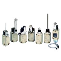
Wide Range of Two-circuit Switches; Select One for the Operating Environment/Application WL/Basic models
Related Contents
- Features
- Lineup
- Specifications
- Dimensions
- Catalog / Manual / CAD / Software
last update: November 9, 2023
Approved Standards
| Agency | Standard | File No. | Approved models |
|---|---|---|---|
| UL | UL508 | E76675 | Contact your OMRON representative
for information on approved models. |
| CSA | CSA C22.2 No.14 | LR45746 | |
| TÜV Rheinland | EN60947-5-1 | J50022353, J9950023, J9950959 | |
| CCC (CQC) | GB/T14048.5 | Contact your OMRON
representative for details. |
General-purpose/Weather-proof Switches
Ratings
Standard-load Switches
| Item | Rated voltage
(V) |
Non-inductive load (A) | Inductive load (A) | ||||||
|---|---|---|---|---|---|---|---|---|---|
| Resistive load | Lamp load | Inductive load | Motor load | ||||||
| NC | NO | NC | NO | NC | NO | NC | NO | ||
| Basic models,
overtravel models |
125 VAC
250 VAC 500 VAC |
10
10 10 |
3
2 1.5 |
1.5
1 0.8 |
10
10 3 |
5
3 1.5 |
2.5
1.5 0.8 |
||
| 8 VDC
14 VDC 30 VDC 125 VDC 250 VDC |
10
10 6 0.8 0.4 |
6
6 4 0.2 0.1 |
3
3 3 0.2 0.1 |
10
10 6 0.8 0.4 |
6
6 4 0.2 0.1 |
||||
Note: For details of The WL high-sensitivity, high-precision models, refer to Limit Switch WL-N/WL Datasheet (Cat. No. C151-E1).
Note: 1. The above figures are for steady-state currents.
2. Inductive loads have a power factor of 0.4 min. (AC) and a time constant of 7 ms max. (DC).
3. A lamp load has an inrush current of 10 times the steady-state current.
4. A motor load has an inrush current of 6 times the steady-state current.
5. For PC loads, use the microload models.
| Inrush current | NC | 30 A max. |
|---|---|---|
| NO | 20 A max. |
| Minimum applicable load | 5 VDC 160 mA |
|---|
Microload Switches (Refer to these ratings before using the product.)
| Rated voltage (V) | Rated current (A) - Resistive load |
|---|---|
| AC 125 | 0.1 |
| DC 30 |
Operation in the following ranges will produce optimum performance.
| Recommended load range | 5 to 30 VDC
0.5 to 100 mA |
|---|
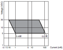
| Recommended load range | 5 VDC 1 mA |
|---|
Approved Standard Ratings
UL/CSA
Standard-load Switches: A600, NEMA
| Rated voltage | Carry current | Current (A) | Volt-amperes (VA) | ||
|---|---|---|---|---|---|
| Make | Break | Make | Break | ||
| 120 VAC
240 VAC 480 VAC 600 VAC |
10 A | 60
30 15 12 |
6
3 1.5 1.2 |
7,200 | 720 |
Microload Switches
0.1 A 125 VAC, 0.1 A 30 VDC
TÜV (EN60947-5-1) (Only models with ground terminals are approved.)
| Model | Application category and ratings | Thermal current (Ithe) | Indicator |
|---|---|---|---|
| WL[] | AC-15: 2 A/250 V
DC-12: 2 A/48 V |
10 A | — |
| WL01[] | AC-14: 0.1 A/125V
DC-12: 0.1 A/48 V |
0.5 A | — |
| WL[]-LE | AC-15: 2 A/250 V | 10 A | Neon lamp |
| WL01[]-LE | AC-14: 0.1 A/125 V | 0.5 A | Neon lamp |
| WL[]-LD | AC-15: 2 A/115 V
DC-12: 2 A/48 V |
10 A | LED |
| WL01[]-LD | AC-14: 0.1 A/115 V
DC-12: 0.1 A/48 V |
0.5 A | LED |
Note: As an example, AC-15: 2 A/250 V means the following:
| Application category | AC-15 |
|---|---|
| Rated operating current (Ie) | 2A |
| Rated operating voltage (Ue) | 250V |
Indicator-equipped Switches
| Item | Max. rated voltage (V) | Leakage current (mA) | |
|---|---|---|---|
| WL-LE | Neon lamp | 125 AC | Approx. 0.6 |
| 250 AC | Approx. 1.9 | ||
| WL-LD | LED | 115 AC/DC | Approx. 0.5 |
| 10 to 24 AC/DC | Approx. 0.4 | ||
Characteristics
| Degree of protection *1 | IP67 (EN60947-5-1) | |
|---|---|---|
| Durability
*2 |
Mechanical | 15,000,000 operations min. *3 |
| Electrical | 750,000 operations min. *4 | |
| Operating speed | 1 mm/s to 1 m/s (in case of WLCA2) | |
| Operating
frequency |
Mechanical | 120 operations/minute min. |
| Electrical | 30 operations/minute min. | |
| Rated frequency | 50/60 Hz | |
| Insulation resistance | 100 MΩ min. (at 500 VDC) | |
| Contact resistance | 25 mΩ max. (initial value for the built-in switch when tested alone) *7 | |
| Dielectric
strength |
Between terminals of the same
polarity |
1,000 VAC, 50/60 Hz for 1 min |
| Between current-carrying metal
part and ground |
2,200 VAC, 50/60 Hz for 1 min/Uimp 2.5 kV | |
| Between each terminal and non-
current-carrying metal part |
2,200 VAC, 50/60 Hz for 1 min/Uimp 2.5 kV | |
| Rated insulation voltage (Ui) | 250 V (EN60947-5-1) | |
| Pollution degree (operating environment) | 3 (EN60947-5-1) | |
| Short-circuit protective device (SCPD) | 10 A, fuse type gG or gI (IEC60269) | |
| Conditional short-circuit current | 100 A (EN60947-5-1) | |
| Conventional enclosed thermal current (Ithe) | 10 A, 0.5 A (EN60947-5-1) | |
| Protection against electric shock | Class I | |
| Vibration
resistance |
Malfunction | 10 to 55 Hz, 1.5-mm double amplitude *5 |
| Shock
resistance |
Destruction | 1,000 m/s2 max. |
| Malfunction | 300 m/s2 max. *5 | |
| Ambient operating temperature | -10°C to +80°C (with no icing) *6 | |
| Ambient operating humidity | 35% to 95% RH | |
| Weight | Approx. 275 g (in case of WLCA2) | |
Note: 1. The above figures are initial values.
2. The figures in parentheses for dielectric strength are those for the microload models.
*1. The degree of protection is tested using the method specified by the standard (EN60947-5-1). Confirm that sealing
properties are sufficient for the operating conditions and environment beforehand.
*2. The values are calculated at an operating temperature of +5°C to +35°C and an operating humidity of 40% to
70%RH. Contact your OMRON sales representative for more detailed information on other operating environments.
*3. Durability is 10,000,000 operations min. for general-purpose overtravel models, and for flexible rod models.
500,000 operations min. for weather-proof models.
*4. Microload models are 1,000,000 operations min. 500,000 operations min. for weather-proof models.
*5. Except flexible rod models. The shock resistance (malfunction) for microload models is 200 m/s2 max.
*6. For low-temperature models this is –40°C to +40°C (with no icing). For heatresistant models the range is +5°C to
+120°C.
*7. For microload models, the contact resistance is 50 mΩ max. (initial value for built-in switch).
Spatter-prevention Switches
Ratings
Screw terminals
| Item | Rated
voltage (V) |
Non-inductive load (A) | Inductive load (A) | ||||||
|---|---|---|---|---|---|---|---|---|---|
| Resistive load | Lamp load | Inductive load | Motor load | ||||||
| NC | NO | NC | NO | NC | NO | NC | NO | ||
| WL[]-LES | 125 VAC
250 VAC |
10
10 |
3
2 |
1.5
1 |
10
10 |
5
5 |
2.5
1.5 |
||
| WL[]-LDS | 115 VAC | 10 | 3 | 1.5 | 10 | 5 | 2.5 | ||
| 12 VDC
24 VDC 48 VDC |
10
6 3 |
6
4 2 |
3
3 1.5 |
10
6 3 |
6
4 2 |
||||
Note: 1. The above figures are for steady-state currents.
2. Inductive loads have a power factor of 0.4 min. (AC) and a time constant of 7 ms max. (DC).
3. A lamp load has an inrush current of 10 times the steady-state current.
4. A motor load has an inrush current of 6 times the steady-state current.
2. Inductive loads have a power factor of 0.4 min. (AC) and a time constant of 7 ms max. (DC).
3. A lamp load has an inrush current of 10 times the steady-state current.
4. A motor load has an inrush current of 6 times the steady-state current.
| Inrush current | NC | 30 A max. |
|---|---|---|
| NO | 20 A max. | |
| Operating temperature | -10°C to +80°C (with no icing) | |
| Operating humidity | 35% to 95%RH max. | |
Approved Standard Ratings
UL/CSA
LE Switches (Neon lamp): A300
| Rated voltage | Carry current | Current (A) | Volt-amperes (VA) | ||
|---|---|---|---|---|---|
| Make | Break | Make | Break | ||
| 120 VAC
240 VAC |
10 A | 60
30 |
6
3 |
7,200 | 720 |
LD Switches (LED)
| Rated voltage | Carry current |
|---|---|
| 115 VAC | 10 A |
| 115 VDC | 0.8 A |
CCC (GB/T14048.5)
| Model | Application category and ratings |
|---|---|
| WL[] | AC-15: 2 A/250 V
DC-12: 2 A/48 V |
| WL01[] | AC-14: 0.1 A/125V
DC-12: 0.1 A/48 V |
| WL[]-LE | AC-15: 2 A/250 V |
| WL01[]-LE | AC-14: 0.1 A/125 V |
| WL[]-LD | AC-15: 2 A/115 V
DC-12: 2 A/48 V |
| WL01[]-LD | AC-14: 0.1 A/115 V
DC-12: 0.1 A/48 V |
Note: As an example, AC-15: 2 A/250 V means the following:
| Application category | AC-15 |
|---|---|
| Rated operating current (Ie) | 2 A |
| Rated operating voltage (Ue) | 250 V |
Characteristics
| Degree of protection *1 | IP67 (EN60947-5-1) | |
|---|---|---|
| Durability
*2 |
Mechanical | 15,000,000 operations min. *3 |
| Electrical | 750,000 operations min. *4 | |
| Operating speed | 1 mm/s to 1 m/s (in case of WLCA2) | |
| Operating
frequency |
Mechanical | 120 operations/minute min. |
| Electrical | 30 operations/minute min. | |
| Rated frequency | 50/60 Hz | |
| Insulation resistance | 100 MΩ min. (at 500 VDC) | |
| Contact resistance | 25 mΩ max. (initial value for the built-in switch when tested alone) | |
| Dielectric
strength |
Between terminals of the same
polarity |
1,000 VAC, 50/60 Hz for 1 min |
| Between current-carrying
metal part and ground |
2,200 VAC, 50/60 Hz for 1 min/Uimp 2.5 kV | |
| Between each terminal and non-
current-carrying metal part |
2,200 VAC, 50/60 Hz for 1 min/Uimp 2.5 kV | |
| Rated insulation voltage (Ui) | 250 V (EN60947-5-1) | |
| Pollution degree (operating environment) | 3 (EN60947-5-1) | |
| Short-circuit protective device (SCPD) | 10 A, fuse type gG or gI (IEC60269) | |
| Conditional short-circuit current | 100 A (EN60947-5-1) | |
| Conventional enclosed thermal current (Ithe) | 10 A, 0.5 A (EN60947-5-1) | |
| Protection against electric shock | Class I | |
| Vibration
resistance |
Malfunction | 10 to 55 Hz, 1.5-mm double amplitude |
| Shock
resistance |
Destruction | 1,000 m/s2 max. |
| Malfunction | 300 m/s2 max. | |
| Ambient operating temperature | -10°C to +80°C (with no icing) | |
| Ambient operating humidity | 35% to 95%RH | |
| Weight | Approx. 275 g (in case of WLCA2) | |
Note: The above figures are initial values.
*1. The degree of protection is tested using the method specified by the standard (EN60947-5-1). Confirm that sealing
properties are sufficient for the operating conditions and environment beforehand.
*2. The values are calculated at an operating temperature of +5°C to +35°C and an operating humidity of 40% to 70%RH.
Contact your OMRON sales representative for more detailed information on other operating environments.
*3. Durability is 10,000,000 operations min. for general-purpose overtravel models.
*4. Microload models are 1,000,000 operations min.
Long-life Switches
Ratings
General Ratings (Refer to these ratings before using the product.)
Screw Terminal Switches
| Item | Rated
voltage (V) |
Non-inductive load (A) | Inductive load (A) | ||||||
|---|---|---|---|---|---|---|---|---|---|
| Resistive load | Lamp load | Inductive load | Motor load | ||||||
| NC | NO | NC | NO | NC | NO | NC | NO | ||
| Basic models,
overtravel models |
115 AC | 10 | 3 | 1.5 | 10 | 5 | 2.5 | ||
| 12 DC
24 DC 48 DC 115 DC |
10
6 3 0.8 |
6
4 2 0.2 |
3
3 1.5 0.2 |
10
6 3 0.8 |
6
4 2 0.2 |
||||
| Inrush current | NC | 30 A max. |
|---|---|---|
| NO | 20 A max. |
Direct-wired Connector and Pre-wired Connector Switches
| Model | Rated
voltage (V) |
Non-inductive load (A) | Inductive load (A) | ||||||
|---|---|---|---|---|---|---|---|---|---|
| Resistive load | Lamp load | Inductive load | Motor load | ||||||
| NC | NO | NC | NO | NC | NO | NC | NO | ||
| DC | 12 DC | 3 | 3 | 3 | 3 | 3 | 3 | 3 | 3 |
| 24 DC | 3 | 3 | 3 | 3 | 3 | 3 | 3 | 3 | |
| 48 DC | 3 | 3 | 3 | 3 | 3 | 3 | 3 | 3 | |
| 115 DC | 0.8 | 0.8 | 0.2 | 0.2 | 0.8 | 0.8 | 0.2 | 0.2 | |
| AC | 115 AC | 3 | 3 | 3 | 1.5 | 3 | 3 | 3 | 2.5 |
Note: 1. The above figures are for steady-state currents.
2. Inductive loads have a power factor of 0.4 min. (AC) and a time constant of 7 ms max. (DC).
3. A lamp load has an inrush current of 10 times the steady-state current.
4. A motor load has an inrush current of 6 times the steady-state current.
2. Inductive loads have a power factor of 0.4 min. (AC) and a time constant of 7 ms max. (DC).
3. A lamp load has an inrush current of 10 times the steady-state current.
4. A motor load has an inrush current of 6 times the steady-state current.
Characteristics
| Degree of protection *1 | IP67 (EN60947-5-1) | |
|---|---|---|
| Durability
*2 |
Mechanical | 30,000,000 operations min. |
| Electrical | 30,000,000 operations min. (10 mA at 24 VDC, resistive load)
750,000 operations min. (10 A at 115 VAC, resistive load) |
|
| Operating speed | 1 mm/s to 1 m/s (in case of WLCA2) | |
| Operating
frequency |
Mechanical | 120 operations/minute |
| Electrical | 30 operations/minute | |
| Rated frequency | 50/60 Hz | |
| Insulation resistance | 100 MΩ min. (at 500 VDC) | |
| Contact resistance | 25 mΩ max. (initial value for the built-in switch when tested alone) | |
| Dielectric
strength (50/60 Hz for 1 min) |
Between terminals of the
same polarity |
1,000 VAC (except connector models) |
| Between current-carrying
metal part and ground |
2,200 VAC (1,500 V) | |
| Between each terminal
and non-current- carrying metal part |
2,200 VAC (1,500 V) | |
| Vibration
resistance |
Malfunction | 10 to 55 Hz, 1.5-mm double amplitude |
| Shock
resistance |
Destruction | 1,000 m/s2 max. |
| Malfunction | 300 m/s2 max. | |
| Ambient operating temperature | -10°C to +80°C (with no icing) | |
| Ambient operating humidity | 35% to 95%RH | |
| Weight | Approx. 275 g (in case of WLCA2) | |
Note: The figures in parentheses for dielectric strength, are those for connector models.
*1. The degree of protection is tested using the method specified by the standard (EN60947-5-1). Confirm that sealing
properties are sufficient for the operating conditions and environment beforehand.
*2. The values are calculated at an operating temperature of +5°C to +35°C, and an operating humidity of 40% to 70%RH.
Contact your OMRON sales representative for more detailed information on other operating environments.
last update: November 9, 2023